Appearance
Hardware Architecture
CoderBot is based on Raspberry Pi computer, equipped with a contorl board "hat".
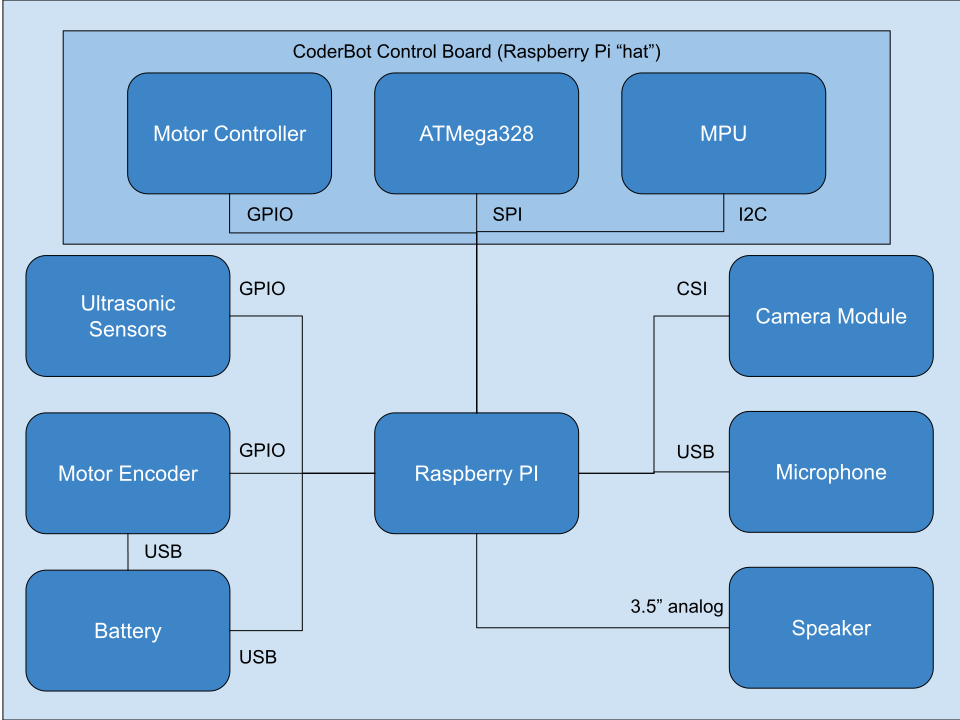
The Raspberry is powered by a lithium-ion powerbank and is connected to an USB microphone, a speaker via the 3.5" audio jack and to the camera module via the CSI port.
Raspberry Pi
CoderBot has been tested with the following Raspberry Pi models:
- Model B 3
- Model B+ 3
- Model A+ 3
No tests has been done with Model B 4, Compute Module 4 and Zero W 2, although they should be compatible with the software.
Micro-SD card
The micro-sd card must have at least 8GB capacity. Class 10 cards are recommended.
Camera module
The camera used is the standard Raspberry Pi camera module "v1" (5 megapixel). The "v2" camera can also be used, as well as special infrared versions.
Control board
The control board contains logic to accomplish the following:
- control motors (DC, PWM)
- control two servos (PWM)
- read encoder data from motors
- control and read ultrasonic sensors
- read MPU (accelerometer/gyroscope/compass) data
- read/write data to the on board atmega328
Microphone
The microphone can be any device with an USB connection.
Speaker
The speaker is connected to the 3.5" headphones output, it must be an amplified speaker with > 1 Watt.
Battery
The battery used is a powerbank with a nominal capacity of 10000mAh and two separate USB outputs, each with 2A nominal output current.
The battery must have separate outputs and a rather large capacity to sustain the peak consumption caused by starting the motors and at the same time supply 5V, 1A to the Raspberry Pi, without any interruptions.